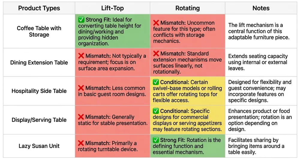
OEM Table Surface Mechanism: Engineering and Tooling Guide for Custom Furniture Projects
Most table mechanism sourcing problems don't start at production. They start earlier — when a buyer submits drawings that haven't been reviewed for manufacturability, or locks an MOQ before understanding how tooling cost is structured, or picks a supplier based on price without knowing whether that factory owns its own tooling. By the time the first sample arrives wrong, the project is already behind.
This guide walks through what OEM table surface mechanism sourcing actually involves: from spec submission and DFM review through tooling build, first-article sampling, and production approval. If you're evaluating suppliers or preparing a custom project, this is the sequence that determines whether your program runs clean or runs expensive.
—
OEM vs ODM: Which Path Fits Your Project
The distinction matters before you contact a single factory.
OEM means you supply the drawings. The factory produces to your specification — geometry, material grade, surface finish, motion type, load rating. Their job is to manufacture what you've designed. A good OEM factory will review your drawings for manufacturability and flag problems before tooling starts, but the design authority stays with you.
ODM means you supply a brief. You tell the factory your target retail price, the market segment, the performance requirements, and any aesthetic direction. The factory develops the mechanism design, builds the tooling, runs samples, and iterates until the spec is locked. You end up with a mechanism that's yours commercially but was engineered on the factory side.
Most buyers in the furniture hardware category land somewhere between the two. They have a reference sample or a rough concept, not a complete drawing package. In that case, the honest path is ODM with a detailed brief — trying to force an incomplete concept through OEM tooling without proper drawings is one of the cleaner ways to waste a tooling budget.
(We see this regularly: a buyer sends a photo of a competitor's mechanism and asks us to "copy it." That's not OEM — that's ODM from a reference. We'll do it, but we need to engineer it properly, not guess at the internal geometry from a photo.)
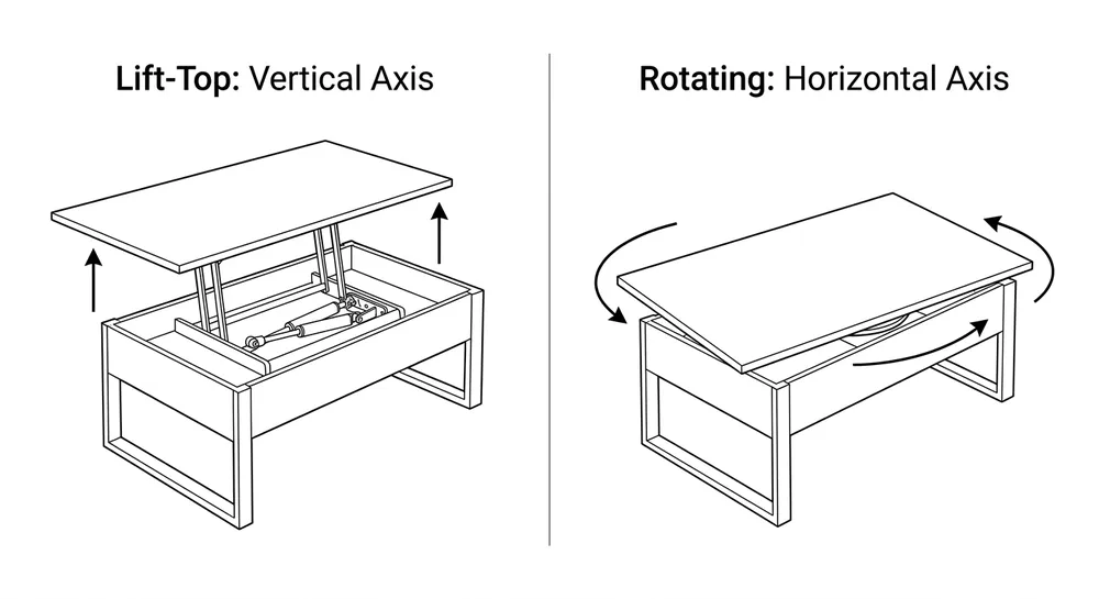
For a lift-top table mechanism or a coffee table mechanism with specific motion requirements, the drawing package needs to be complete before tooling starts. What "complete" means is covered in the next section.
—
What Must Be Locked Before Tooling Starts
Tooling revisions are expensive. A die change on a stamped bracket can run $300–800 depending on complexity. A full tool rebuild on a die-cast component costs more. The way to avoid revision costs is to lock every decision-relevant spec before the tool is cut — not after the first sample comes back wrong.
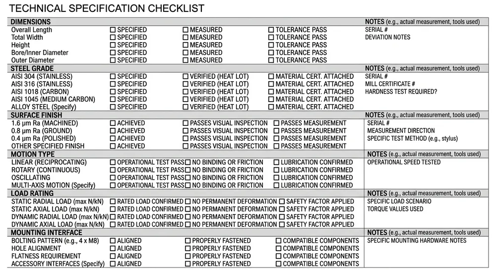
Here's what needs to be confirmed before a responsible factory will start tooling:
| Spec Category | What to Lock | Why It Matters |
|---|---|---|
| Dimensions | Overall envelope, mounting hole pattern, pivot locations | Determines tool geometry — changes after cutting require rework |
| Steel grade | Cold-rolled grade, thickness per component | Affects spring-back in stamping, weld penetration, load performance |
| Surface finish | Plating type, powder coat color, film thickness | Plating adds dimensional thickness — affects fit on tight-clearance parts |
| Motion type | Lift angle, travel distance, resistance profile | Drives spring rate selection and pivot geometry |
| Load rating | Static load, dynamic cycle requirement | Sets material gauge and structural joint spec |
| Mounting interface | Table top attachment method, underframe clearance | Determines bracket geometry and hardware spec |
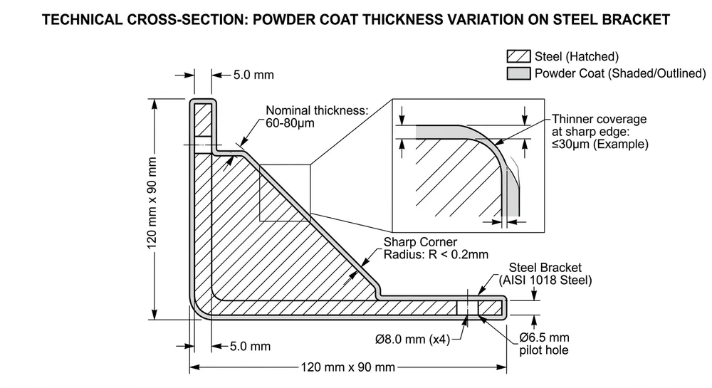
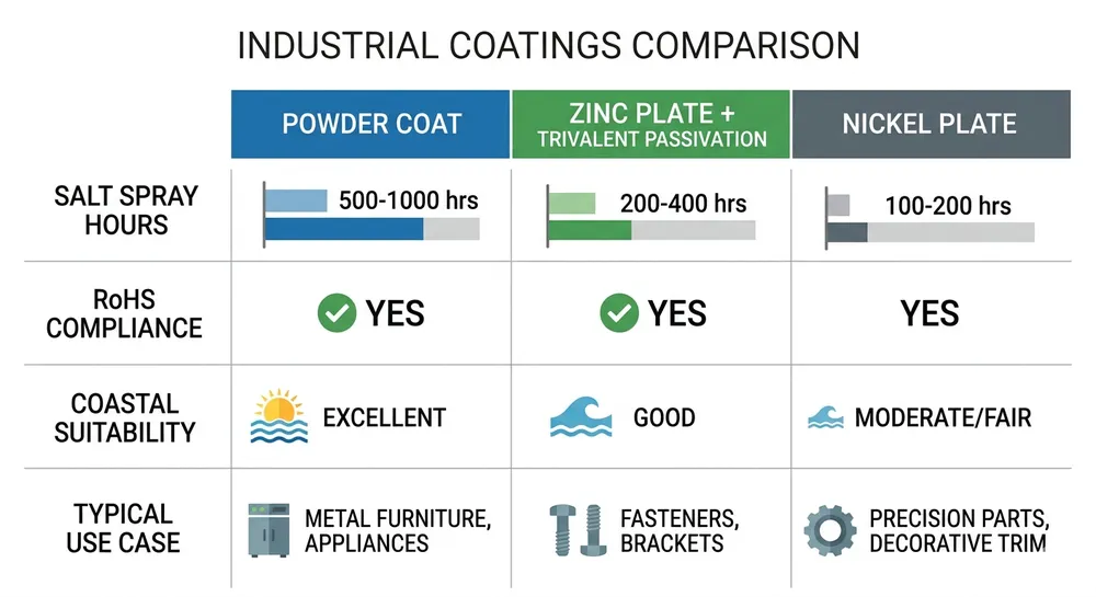
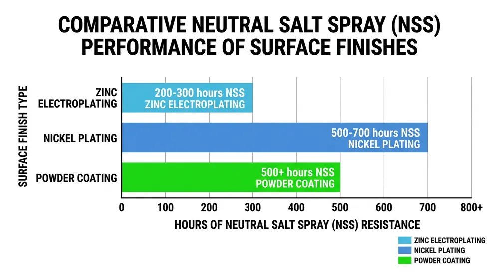
The surface finish decision catches buyers more often than the others. Powder coating adds 60–80μm per side. On a mechanism with tight clearance between moving parts, that's enough to cause binding if the coating spec isn't factored into the drawing tolerances. Nickel and zinc plating add less thickness but still need to be accounted for on precision-fit components. Lock the finish before the tool is cut, not after the sample comes back stiff.
—
Steel Grade Selection in OEM Table Mechanisms
This is the spec that gets under-specified most often on table mechanism projects, and it's the one that causes the most downstream problems.
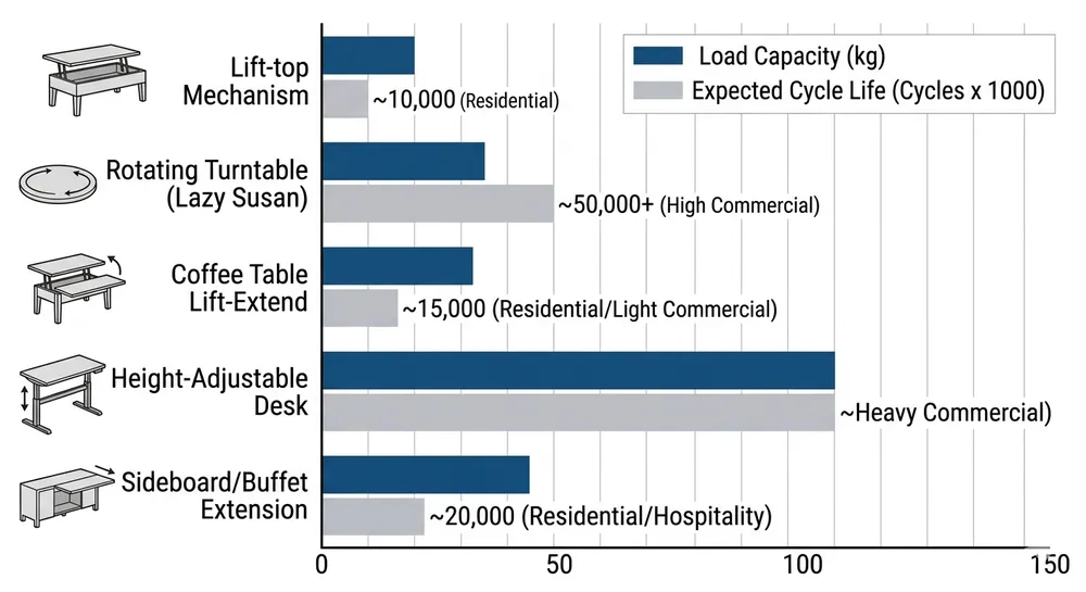
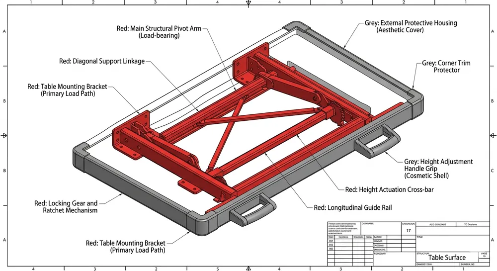
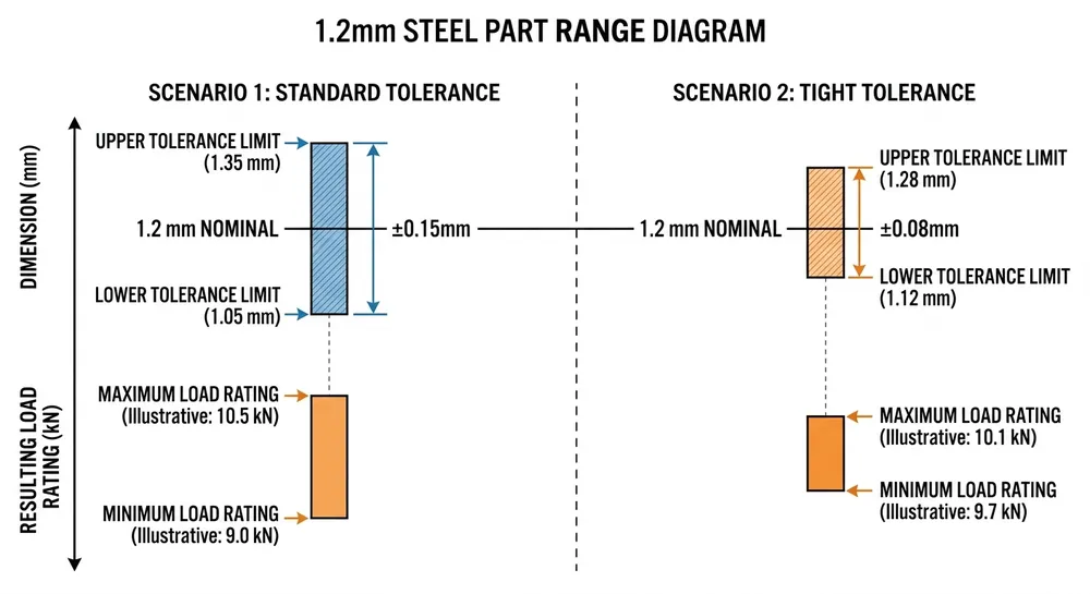
The structural plates and brackets in a table surface mechanism are typically stamped from cold-rolled steel coil. The two grades that cover most commercial applications are SPCC (JIS G3141) and SPCD — SPCC for standard structural components, SPCD where deeper draws or tighter forming radii are required. For load-bearing pivot brackets on lift-top mechanisms, we typically run 2.0–2.5mm SPCC. Lighter linkage arms and guide plates can run 1.2–1.5mm depending on the load spec.
Where buyers get into trouble is specifying gauge without specifying grade, or specifying grade without confirming the supplier's incoming material certification process. A factory running unverified coil stock can produce parts that pass dimensional inspection but fail load-cycle testing because the actual material hardness is outside spec. We check mill certificates on every coil and pull hardness samples on first-article parts from each new coil — that's the check that catches substitution before it becomes a field failure.
For zinc alloy die-cast components — adjustment knobs, pivot collars, decorative covers — the standard alloy is Zamak 3 or Zamak 5. Zamak 5 has higher tensile strength and is the right choice for components under repeated mechanical stress. The difference matters on a lift-top mechanism where the adjustment collar takes load every time the surface is raised. Specifying "zinc alloy" without the alloy grade leaves the decision to the factory, and not every factory will default to the stronger option.
(We switched our standard pivot collar spec to Zamak 5 across the table mechanism range after seeing fatigue cracking on Zamak 3 parts in a high-cycle commercial application. The material cost difference is small. The warranty claim cost is not.)
—
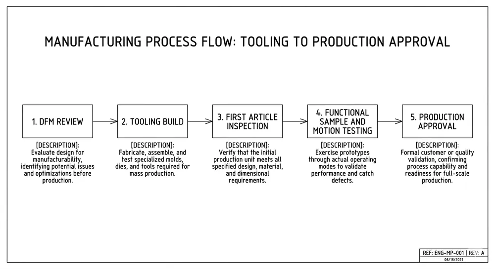
The OEM Tooling and Sampling Workflow
Understanding this sequence protects your budget and your timeline. Factories that skip steps in this workflow are the ones that deliver production parts that don't match the approved sample.
Step 1 — DFM Review
Before any tool is cut, the factory's engineering team reviews your drawings for design for manufacturability. This is where problems get caught cheaply. Common DFM flags on table mechanism projects: bend radii too tight for the specified steel gauge, hole patterns that conflict with progressive die strip layout, surface finish specs that don't account for coating thickness on mating parts, pivot geometry that creates interference at the end of the motion arc.
A factory with mechanism-specific engineers will catch these. A factory with generalist engineers — or no DFM review at all — will cut the tool and let the sample tell you what's wrong.
Step 2 — Tooling Build
For stamped components, tooling is a progressive die — a multi-station tool that forms the part through a sequence of punching, bending, and cutting operations in a single press stroke. Build time for a typical mechanism bracket tool runs 3–5 weeks depending on complexity. Die-cast tooling for smaller components runs 2–4 weeks.
Factories that build tooling in-house can turn revision cycles in days. Factories that outsource tooling to third-party shops add a communication layer and a logistics delay to every revision — which matters when you're on sample iteration two or three and the project is already behind schedule.
Step 3 — First Article Inspection
The first parts off the new tool go through dimensional inspection against the drawing. Every critical dimension gets measured and recorded. This is not a visual check — it's a documented dimensional report that confirms the tool is producing to spec before any further parts are run.
If dimensions are out, the tool goes back for adjustment. This is normal. Most tools need at least one correction pass. The question is how fast the factory can turn it.
Step 4 — Functional Sample and Motion Testing
Once first-article dimensions are confirmed, a small assembly run produces functional samples for motion testing. For a lift-top mechanism, this means checking the full travel arc, the resistance profile at each point in the motion, the lock engagement (if applicable), and the load rating under static and dynamic conditions.
This is also the stage where surface finish samples are approved — color, texture, and adhesion on the actual production coating run, not a reference panel.
Step 5 — Production Approval and Golden Sample
When the functional sample is approved, a golden sample is sealed and retained by both parties. Production runs against that reference. Any deviation from the golden sample at outgoing inspection is a hold — not a judgment call.
—
MOQ and Tooling Cost: How the Honest Number Works
The MOQ on an OEM table mechanism project is a function of tooling amortization, not an arbitrary round number.
Here's the structure: tooling has a fixed cost — let's say $2,000–4,000 for a typical stamped bracket set plus a die-cast component tool. That cost needs to be recovered across the production run. If you want to amortize it over 500 units, the per-unit tooling contribution is $4–8. Over 1,000 units, it's $2–4. Over 2,000 units, it's $1–2.
The factory's honest MOQ is the quantity at which the tooling amortization per unit reaches a level that doesn't make the landed cost unworkable for your market. A factory quoting 500 units MOQ on a complex OEM mechanism with $3,500 in tooling is either absorbing the tooling cost (unlikely) or building it into the unit price in a way that's not transparent.
We give buyers the tooling cost and the unit price separately, and we'll show the amortization math. If your volume doesn't support the tooling investment at a unit price that works for your margin, we'll tell you that before you commit — not after the tool is built.
For standard catalog Table & Surface Mechanism items, MOQ is 500 units with no tooling cost. For OEM projects with new tooling, the minimum depends on the spec. A simple bracket modification to an existing tool is different from a full custom mechanism with three new tools.
—
Where OEM Table Mechanisms Fail: The Quality Failure Points
Most OEM quality failures on table mechanisms trace back to three sources. Knowing them helps you evaluate a supplier's real capability before you place a tooling deposit.
Die-cast component dimensional drift
The adjustment collar, pivot housing, or decorative cover — whichever die-cast component is in the assembly — is the most common source of batch-to-batch inconsistency. Die-cast tooling wears, and factories that outsource casting to third-party foundries often don't have visibility into tool condition or process parameters. The result is parts that are within tolerance on the first production run and out of tolerance on the third.
Factories with in-house die-casting control the tool maintenance schedule, the alloy temperature, and the injection parameters. When a dimension drifts, they find it at incoming inspection, not when your customer reports a loose-fitting mechanism.
Weld joint failure under load cycling
Structural welds on load-bearing brackets are the second failure point. MIG welding on mechanism assemblies requires consistent penetration — a weld that looks clean on the surface but has incomplete fusion will pass visual inspection and fail under repeated load cycling. Pull-test verification on structural joints, not just visual inspection, is the check that catches this.
Surface finish adhesion failure at weld seams
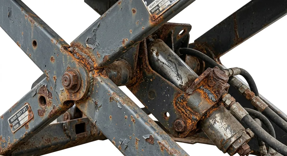
Powder coat adhesion fails most often at weld seams, where surface contamination from welding flux and heat-affected zone oxidation creates a poor substrate for coating adhesion. The fix is grinding and chemical pre-treatment at every weld seam before the part enters the coating line. Factories that skip this step produce parts that look fine at shipment and develop coating delamination in the field within 12–18 months.
We grind every structural weld seam and run a phosphate pre-treatment before powder coating on all mechanism assemblies. It adds process time. It also means we don't get adhesion failure claims.
—
Evaluating an OEM Supplier's Real Engineering Capability
Price and lead time are easy to compare. Engineering capability is harder to assess from a quotation. Here's what to look for.
Does the factory own its tooling?
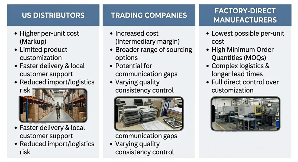
Ask directly. A factory that owns its tooling can show you the tool, tell you its current condition, and turn revisions without involving a third party. A factory that outsources tooling will give you longer revision cycles and less transparency on tool maintenance.
Does the engineering team have mechanism-specific experience?
General metal fabrication experience doesn't transfer cleanly to furniture mechanism design. Spring rate selection, pivot geometry, motion arc calculation, and die-cast wall thickness for mechanism components are specialized knowledge. Ask what mechanism types the engineering team has developed tooling for, and ask to see DFM review documentation from a previous project.
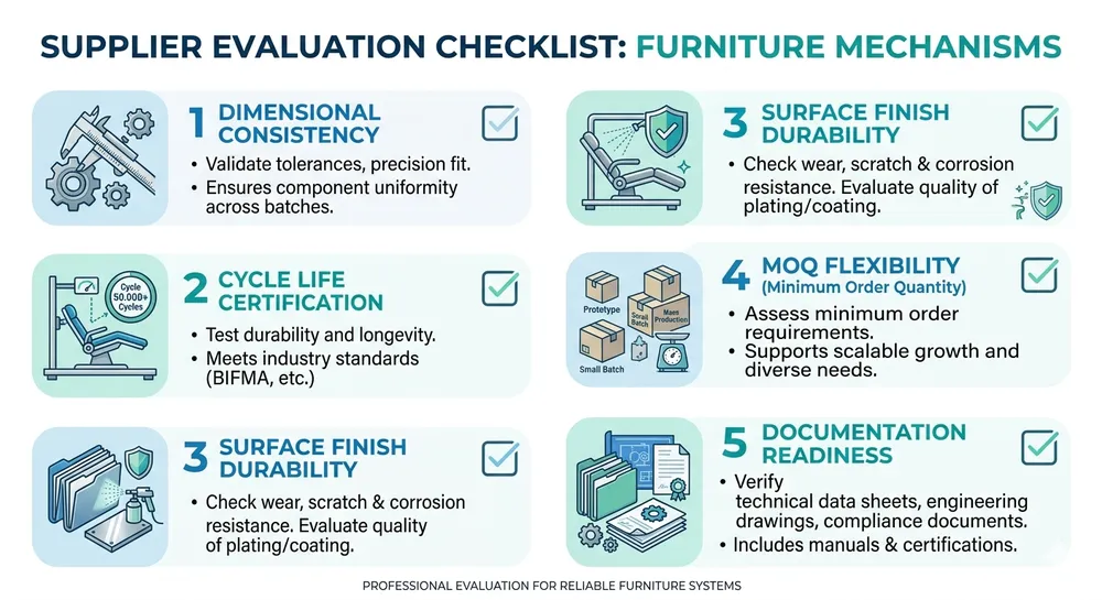
What does the QC process look like at each stage?
A supplier that can only describe outgoing inspection doesn't have a real quality system — they have a sorting operation. The checkpoints that matter are incoming material verification, first-article dimensional inspection, in-process weld and assembly checks, and 100% functional testing before packing. Ask for the inspection records from a recent production run.
Can they show you a golden sample retention process?
If a factory doesn't retain golden samples with documented approval records, there's no reference point for production conformance. This is a basic OEM quality control requirement, and its absence tells you something about how the factory manages production consistency.
| Evaluation Criterion | What to Ask | Red Flag |
|---|---|---|
| Tooling ownership | "Do you build tooling in-house?" | "We work with tooling partners" |
| Engineering depth | "Who reviews drawings for DFM?" | No dedicated engineering team |
| QC checkpoints | "Walk me through your inspection stages" | Only outgoing inspection described |
| Golden sample process | "How do you retain production references?" | No documented golden sample system |
| Material verification | "How do you verify incoming steel grade?" | Visual check only, no mill cert review |
—
Frequently Asked Questions
What's the difference between OEM and ODM for table mechanisms, and which should I choose?
OEM means you supply complete engineering drawings and the factory manufactures to your spec. ODM means you supply a brief — performance requirements, target price, market segment — and the factory develops the design. If you have a complete, reviewed drawing package, OEM is the right path. If you have a reference sample, a concept, or a performance requirement without detailed drawings, ODM will get you to a better result faster and with less tooling revision cost.
How much does OEM table mechanism tooling typically cost?
Tooling cost depends on the number of components requiring new tools and the complexity of each. A single stamped bracket tool runs roughly $800–1,500. A die-cast component tool runs $1,200–2,500. A complete custom mechanism with three or four new tools typically runs $3,000–6,000 total. These are amortized into the unit price over the production run — we quote tooling cost and unit price separately so the math is transparent.
What steel grade should I specify for a lift-top table mechanism?
For structural load-bearing brackets and plates, SPCC cold-rolled steel at 2.0–2.5mm is the standard spec for commercial-grade lift-top mechanisms. Lighter linkage components can run 1.2–1.5mm. For die-cast components under repeated mechanical stress — pivot collars, adjustment hardware — specify Zamak 5 rather than generic "zinc alloy." The alloy grade matters for fatigue life on high-cycle applications.
What's the minimum order quantity for a custom OEM table mechanism?
There's no universal answer — it depends on tooling cost and your target unit price. We calculate MOQ based on tooling amortization at a unit price that works for your market. For a simple OEM modification to an existing tool, MOQ can be as low as 500 units. For a full custom mechanism with new tooling, the honest minimum is typically 1,000–2,000 units depending on the spec. We'll show you the math before you commit.
How long does the OEM tooling and sampling process take?
DFM review runs 3–5 business days for a complete drawing package. Tooling build is 3–5 weeks for stamped components, 2–4 weeks for die-cast tools. First-article inspection and functional sampling add 1–2 weeks. Total from drawing approval to production-ready sample: typically 6–10 weeks depending on revision cycles. The variable is how many sample iterations are needed — which is why locking specs before tooling starts matters.
What documents should I request from an OEM table mechanism supplier?
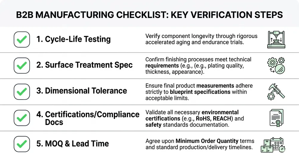
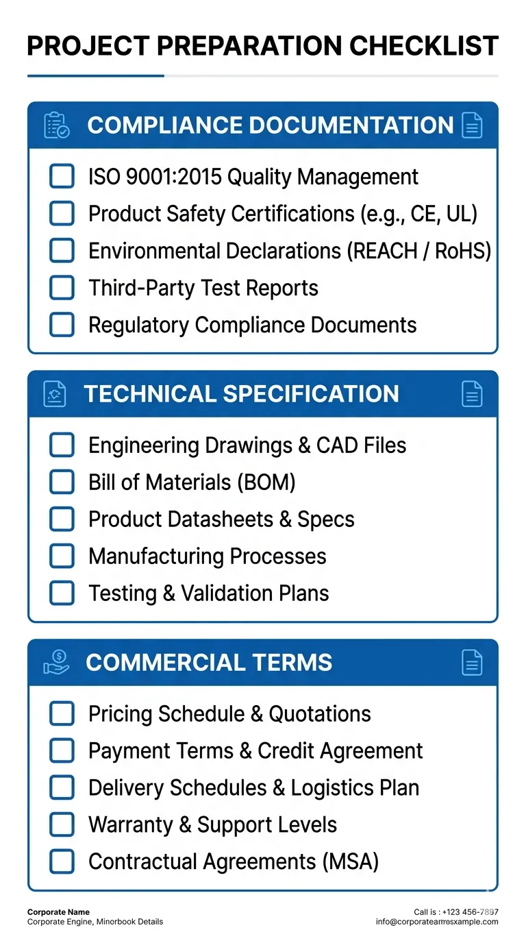
At minimum: material test certificates (MTCs) for steel and zinc alloy, first-article dimensional inspection report, functional test report for the approved sample, and CE or SGS test reports if your market requires them. For buyers supplying into the EU, request the declaration of conformity. For North American importers, request the material compliance documentation your customs broker needs for HTS classification.
—
If your project is at the drawing review stage or you're evaluating whether your current spec is manufacturable, send us your drawings or project brief — mechanism type, load requirement, surface finish, and target market. We'll run a DFM review and come back with a specific quote and any flags worth addressing before tooling starts.