Most sourcing problems with chair mechanisms don't start on the production floor. They start with a diagram that nobody read carefully enough.
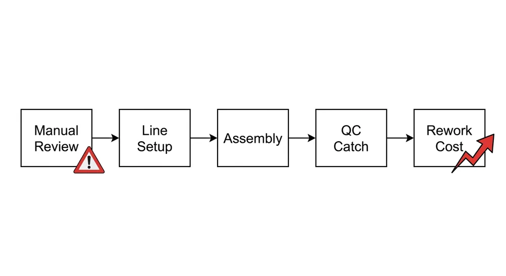
We see it regularly: a buyer sends over a drawing, we quote it, production runs — and then the first container arrives with mechanisms that don't fit the chair base, or the tilt tension is wrong for the weight class, or the gas lift collar is 2mm off and the whole assembly wobbles. Every one of those problems was visible in the original diagram. The information was there. It just wasn't checked.
This article walks through how to read a chair mechanism diagram the way a factory engineer reads it — not as a picture of a product, but as a contract between your spec and our production.

What a Chair Mechanism Diagram Actually Shows
A chair mechanism diagram is not a product photo. It's a manufacturing instruction set. Every line, number, and symbol on it carries a production consequence.
At minimum, a complete diagram should show:
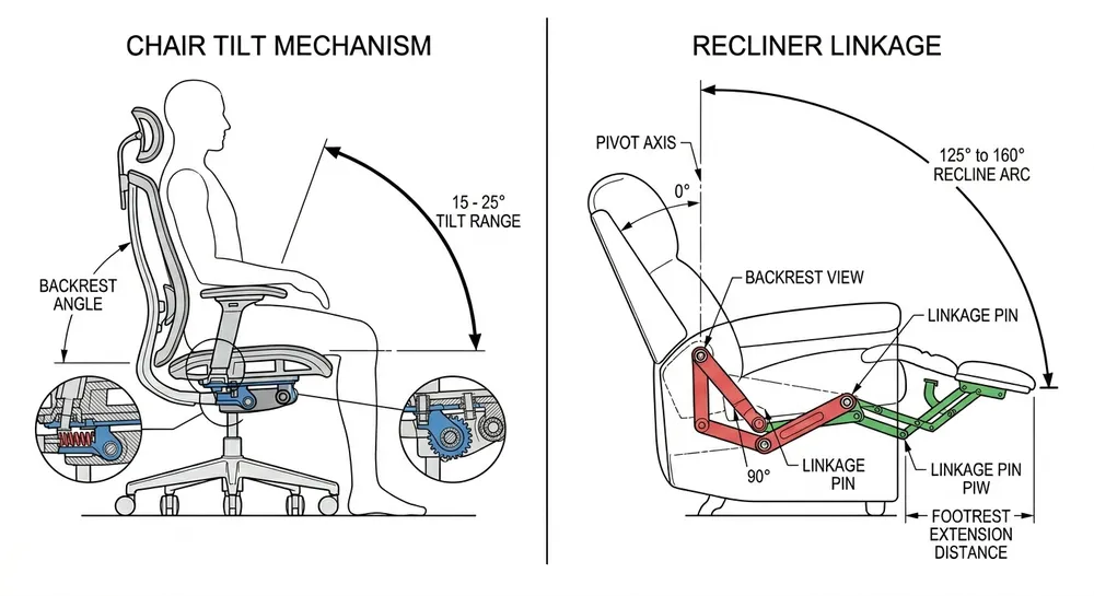
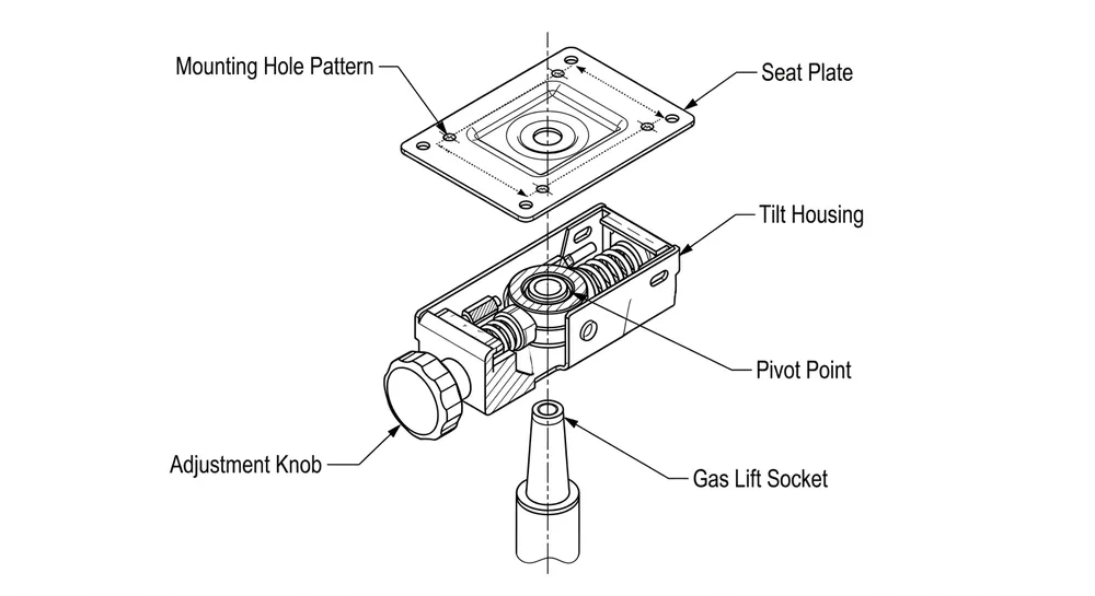
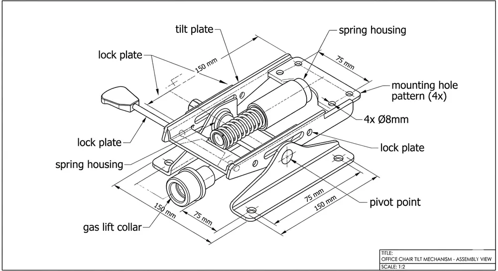
- Part geometry and assembly relationships — how the tilt plate, lock plate, and spring housing connect and move relative to each other
- Critical dimensions — hole center distances, plate thickness, pivot point location, gas lift collar bore diameter
- Tolerance callouts — the acceptable deviation on each critical dimension (e.g., ±0.15mm on the gas lift bore)
- Surface treatment specification — zinc plating, nickel plating, powder coat, or bare steel, and where each applies
- Material callout — steel grade, thickness, and in some cases the forming process (stamped vs. cast)
- Cycle life or load rating — sometimes shown in a title block or notes section, sometimes absent (which is itself a red flag)
If your diagram is missing any of these, you're not giving a factory enough information to quote accurately — and you're not giving yourself enough information to verify what you receive.
The Five Zones Every Buyer Should Check
When we receive a diagram for review, we work through it in zones. Here's the same sequence you should use before sending anything for quoting.
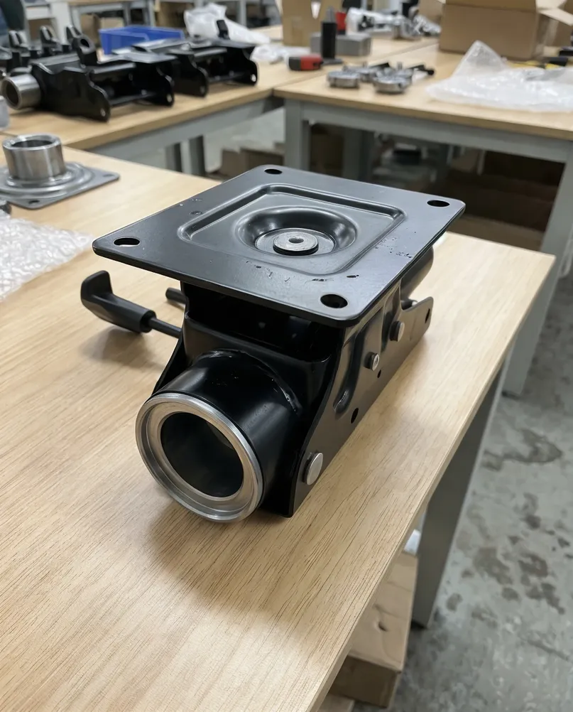
Zone 1: The tilt plate geometry
The tilt plate is the structural backbone of the mechanism. Its dimensions determine whether the mechanism fits your chair base and whether it can handle the load class you're targeting.
Check: overall length and width, plate thickness (typically 3.0–4.5mm cold-rolled steel for standard commercial mechanisms), and the position of the pivot point relative to the mounting holes. A pivot point that's shifted even 3–4mm from spec changes the tilt feel entirely — the mechanism will either feel too stiff or too loose at the same spring tension.
Zone 2: The mounting hole pattern
This is the dimension buyers most often under-specify. The mounting hole pattern — the center-to-center distances between the four base attachment holes — must match your chair base exactly. Standard patterns run 67×67mm or 70×70mm, but there's no universal standard, and a 3mm mismatch means the mechanism won't bolt in.
(We've had buyers discover this after 2,000 units were already stamped. The tooling correction cost more than the original order. Lock this dimension before production starts.)
Check: hole diameter, center-to-center spacing in both axes, and whether the drawing specifies countersink or through-hole.
Zone 3: The gas lift interface
The gas lift collar bore is one of the tightest-tolerance features on the whole mechanism. A standard gas lift cylinder is 50mm diameter, but the bore tolerance on the collar determines whether the cylinder seats firmly or rattles. We hold ±0.15mm on this bore in our stamping process — anything looser and you get audible play in the seat under load.
Check: bore diameter, tolerance callout, and whether the collar is a separate welded component or formed integrally with the tilt plate. Welded collars allow tighter positional control; integral formed collars are faster to produce but harder to hold to tight tolerances on high-volume runs.

Zone 4: The lock plate and tilt tension spring housing
The lock plate controls the tilt-lock function. Its geometry — specifically the engagement depth and the spring preload position — determines how many lock positions the mechanism offers and how positive the lock feels under body weight.
Check: lock plate thickness (typically 2.0–3.0mm), the spring housing dimensions, and whether the diagram specifies spring wire diameter and free length. If the spring spec is missing, the factory will substitute a standard spring — which may or may not match your target tilt resistance for your weight class. For mechanisms targeting heavier users (100kg+), this matters.
Zone 5: The surface treatment callout
Surface treatment is where diagrams most often go silent. A drawing that shows the geometry perfectly but says nothing about surface finish leaves the factory to default — and factory defaults vary.
Check: does the diagram specify the treatment type (zinc plating, nickel plating, powder coat), the coverage area (full surface vs. selective), and any thickness or adhesion standard? For export to North America or Europe, buyers often need to confirm RoHS compliance on plating chemistry. A diagram that just says "zinc plated" without specifying trivalent vs. hexavalent chrome is a compliance gap waiting to happen.
Tolerance Callouts: What the Numbers Mean for Your Order
Tolerances on a mechanism diagram are not suggestions. They define the acceptable production window — and they directly affect your downstream assembly cost.
| Dimension | Typical Tolerance | What Goes Wrong If Missed |
|---|---|---|
| Gas lift collar bore | ±0.15mm | Seat wobble, cylinder rattle under load |
| Mounting hole position | ±0.20mm | Mechanism won't align with chair base |
| Pivot point location | ±0.30mm | Tilt feel inconsistent across batch |
| Plate thickness | ±0.10mm | Load capacity variance, cycle life reduction |
| Lock plate engagement depth | ±0.20mm | Inconsistent lock feel, premature wear |
When a diagram has no tolerance callouts, the factory applies its own defaults. Our defaults are tight — we run progressive die stamping with ±0.15mm capability on critical features — but not every factory's defaults match yours. If you're sourcing from multiple suppliers, unspecified tolerances mean you'll get different products from each one.

What "Cycle Life" on a Diagram Means for Your Warranty Exposure
Cycle life is the number of full tilt-and-return cycles a mechanism is rated to survive before functional failure. It's sometimes shown in the title block of a technical drawing, sometimes in a separate spec sheet, and sometimes not specified at all.
For commercial office seating, 50,000 cycles is a common baseline. For heavy-duty or 24-hour-use applications, buyers typically specify 80,000–100,000 cycles. We load-test every mechanism batch to the rated cycle count before shipment — but we can only test to what's specified.
If your diagram doesn't include a cycle life requirement, you have no basis for a warranty claim if mechanisms fail early. More practically: you have no way to compare quotes from different factories, because they may be quoting different durability levels at the same unit price.
Before you send a diagram for quoting, add the cycle life requirement to the notes section. It takes one line and it closes a significant sourcing risk.
Common Diagram Errors That Cause Production Problems
These are the gaps we see most often when buyers send drawings for review. None of them are exotic — they're just easy to miss if you're not reading the diagram as a production document.
Missing hole tolerances. The hole positions are dimensioned, but no tolerance is called out. The factory applies its own standard. If you're assembling mechanisms into a chair base on a production line, even ±0.5mm variation across a batch creates fitment inconsistency.
Unspecified surface finish on internal surfaces. The external faces are called out for zinc plating, but the spring housing interior and pivot bore are left blank. Bare steel in a pivot bore corrodes under humidity, which increases tilt resistance over time and generates warranty claims from your customers.
Ambiguous pivot geometry. The pivot point is shown as a circle on the drawing, but the bore diameter, tolerance, and shaft fit (clearance vs. interference) aren't specified. We've seen this cause audible creaking in mechanisms that were otherwise dimensionally correct — the shaft was floating in an oversized bore.
No material callout on the lock plate. The tilt plate material is specified, but the lock plate just says "steel." Lock plate hardness affects wear rate at the engagement surface. A soft lock plate wears faster, which means the lock feel degrades over the product's service life. Specify the steel grade and, if needed, the surface hardness after heat treatment.
Revision history absent. If you're sending a revised drawing, make sure the revision block is updated. We've quoted from superseded drawings more than once because the buyer sent the wrong file version. A clear revision block with date and change description prevents this.
How to Send a Diagram for Manufacturability Review
When you're ready to send a drawing for quoting, the package should include:
- The diagram itself — PDF or DWG, with all dimensions, tolerances, and notes visible. Not a photo of a printed drawing.
- Material specification — steel grade, thickness, and any heat treatment requirements
- Surface treatment spec — type, coverage, thickness standard, and compliance requirement (RoHS, REACH, etc.)
- Cycle life requirement — the rated cycle count for your target application
- Target market — this affects which certifications matter. CE for Europe, BIFMA for North America. We can advise on what testing is needed once we know the market.
- Annual volume estimate — this determines whether custom tooling makes sense. For OEM/ODM projects, we review drawings for manufacturability and advise on tooling investment vs. per-unit cost trade-offs. See our OEM ODM chair mechanism process for how that works.
The more complete the package, the faster we can return a quote with grade, tolerance, and surface treatment recommendations — and the less likely you are to receive a first sample that doesn't match your intent.
(We typically return a manufacturability review within 2 business days for standard mechanism drawings. Complex OEM geometries take longer, but we'll tell you upfront.)
FAQ
What's the difference between a chair mechanism diagram and a chair mechanism schematic?
In practice, buyers use both terms for the same document — a 2D technical drawing showing part geometry, dimensions, and assembly relationships. "Schematic" sometimes implies a more simplified representation (showing functional relationships without full dimensional detail), while "diagram" or "technical drawing" implies a fully dimensioned production document. For sourcing purposes, you want the fully dimensioned version with tolerance callouts, not a schematic.
Can I send a competitor's mechanism for reverse engineering?
Yes. We receive physical samples regularly and can produce measured drawings from them. The process involves full dimensional inspection, tolerance assignment based on function, and a manufacturability review before we commit to tooling. This is a standard part of our OEM ODM chair mechanism service.
What tolerance should I specify for the gas lift collar bore if I'm not sure?
For standard 50mm gas lift cylinders, specify Ø50 +0.1/0mm (H7 fit). This gives a light interference to clearance fit that holds the cylinder firmly without requiring force to insert. If you're using a non-standard cylinder diameter, send us the cylinder spec and we'll recommend the bore tolerance.
My diagram has no cycle life callout. What's the default?
There is no universal default. Different factories assume different baselines. Our standard production mechanisms are tested to 50,000 cycles, but if you need 80,000 or 100,000 cycles for a commercial or heavy-duty application, that needs to be specified — it affects material selection, spring spec, and lock plate hardness. Don't assume the factory's default matches your warranty commitment to your customers.
What certifications do I need for chair mechanisms exported to Europe?
CE marking is required for office chairs sold in the EU, which means the mechanism must comply with EN 1335 (office chairs) or EN 16139 (non-domestic seating) depending on the application. The mechanism itself isn't CE-marked independently — the chair manufacturer is responsible for the final product certification — but the mechanism's load ratings and cycle life must support the chair's certification claims. We can provide test reports and material certifications to support your CE documentation package.
If your diagram is ready or you have a sample mechanism you want quoted, send it through our Request Quote form with the spec details above. Our engineering team reviews every drawing before production starts.