A wrong assumption about a drawing costs more than a wrong assumption about price. We've seen buyers approve a mechanism drawing, place a 2,000-unit order, and discover at goods inspection that the tilt resistance was spec'd for a 90 kg load limit — not the 120 kg their market requires. The drawing was technically correct. The buyer just didn't know which numbers to check.
This article walks through what a chair mechanism drawing actually contains, which dimensions and callouts directly affect your sourcing risk, and what to confirm with your supplier before production starts.

What a Chair Mechanism Drawing Actually Contains
Most buyers receive a drawing as a PDF and treat it as a visual confirmation that the part looks right. That's the wrong way to use it.
A complete chair mechanism drawing is a manufacturing contract. Every line, number, and symbol is an instruction to the factory floor. When you sign off on a drawing, you're approving the tolerances, the material grade, the surface treatment, and the load path — not just the shape.
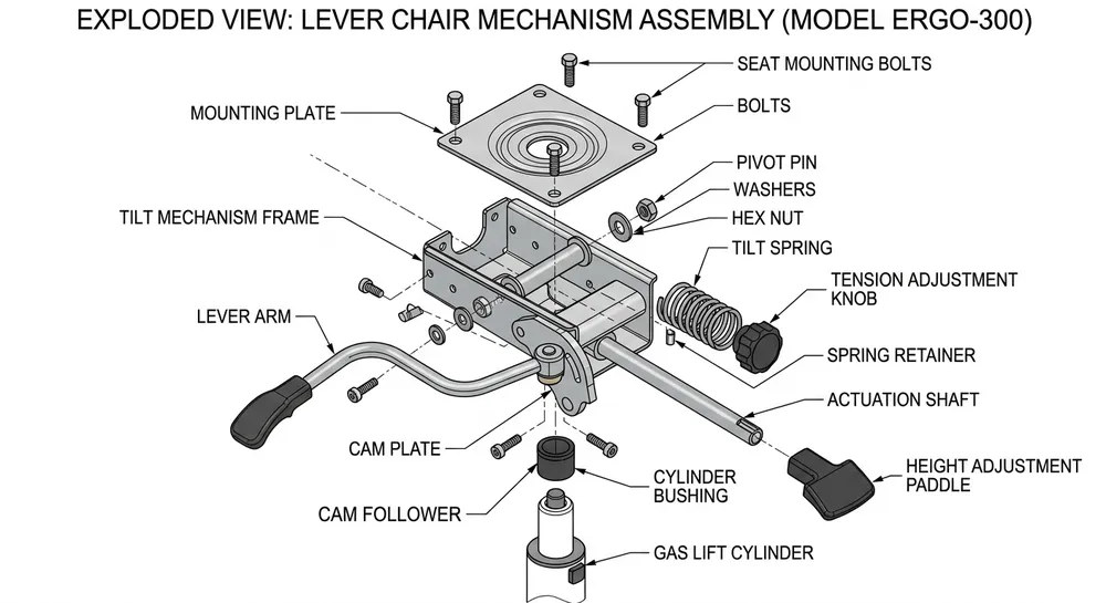
A standard Chair Mechanism drawing package includes:
| Drawing Element | What It Specifies | Why It Matters to You |
|---|---|---|
| Overall assembly dimensions | Mounting footprint, height range, travel limits | Compatibility with your chair base and seat plate |
| Part tolerances (±mm) | Acceptable dimensional variation per component | Affects fit, function, and batch consistency |
| Material callouts | Steel grade, zinc alloy spec, or casting standard | Determines load capacity and corrosion resistance |
| Surface treatment spec | Plating type, coating thickness, salt spray rating | Affects warranty exposure in your target market |
| Load rating / test standard | Static load, dynamic cycle count, test method | The number your downstream buyers actually care about |
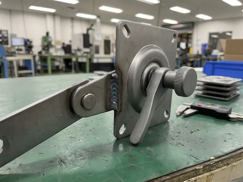
| Weld symbols | Joint type, weld size, inspection requirement | Structural integrity at the highest-stress points |
| Hardware callouts | Bolt grade, spring spec, fastener standard | Affects assembly consistency and field failure rate |
If any of these elements are missing or marked "TBD," the drawing is incomplete. Don't approve it.
The Dimensions That Actually Determine Fit
Mechanism drawings carry dozens of dimensions. Most of them are manufacturing references. A handful of them determine whether the mechanism fits your chair and functions correctly in your market.
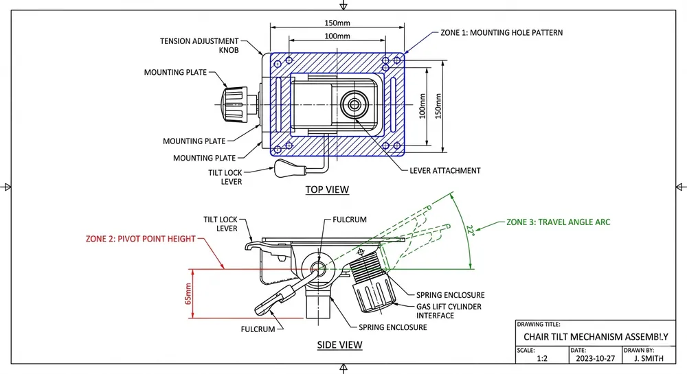
Mounting hole pattern — the bolt circle diameter and hole spacing on the seat plate interface. This is the first thing to check against your chair base spec. A 2 mm deviation here means the mechanism won't mount without modification.
Pivot point height — the distance from the floor reference plane to the tilt axis. This controls the ergonomic feel of the chair. Buyers sourcing for office furniture markets with specific ergonomic standards (EN 1335 in Europe, BIFMA in North America) need this number to fall within a defined range.
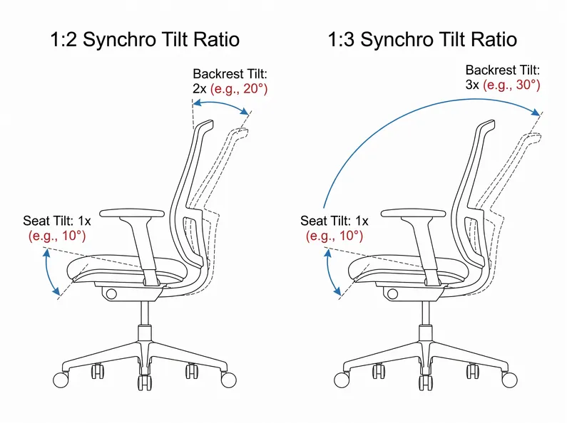
Travel angle — the forward and backward tilt range in degrees. Standard office mechanisms run 3–5° forward, 12–15° back. If your market expects a "synchro" feel, the drawing should show a seat-to-back ratio callout, not just a single travel angle.
Seat plate thickness and flatness tolerance — thin seat plates (under 2.0 mm) flex under load, which causes the mechanism to feel loose over time. We run our standard seat plates at 2.5 mm SPCC with a flatness tolerance of ±0.3 mm across the full plate. (Buyers who've had warranty claims about "wobbly chairs" after 6 months — this is usually where the problem started.)
Material Callouts: What the Drawing Should Tell You
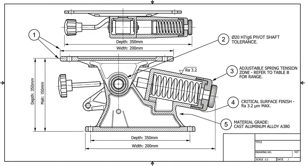
The material callout is one of the most commonly under-specified elements in mechanism drawings from smaller suppliers. You'll see "steel" or "iron casting" with no grade reference. That's not a specification — it's a placeholder.
For stamped steel components (seat plates, back brackets, tilt housings), the drawing should specify:
- Steel grade: SPCC (JIS G3141) for standard commercial use, or SPHC for heavier-gauge structural parts. Some drawings reference Q235 — acceptable, but confirm the actual mill certificate matches.
- Thickness: Nominal thickness plus tolerance (e.g., 2.5 mm ±0.1 mm). Nominal alone isn't enough.
- Pre-treatment: Phosphate or zinc phosphate before surface coating. If the drawing only says "powder coat" with no pre-treatment callout, ask.
For die-cast zinc alloy components (adjustment knobs, tension control housings, decorative covers):
- Alloy grade: Zamak 3 (ASTM B86 AG40A) is the standard. Zamak 5 for higher-strength applications. Drawings that just say "zinc alloy" without a grade are leaving the material decision to the factory floor — which means it'll be made from whatever's cheapest that week.
We switched our tension control housings from Zamak 3 to Zamak 5 in 2021 after seeing micro-cracking on high-cycle units in the 100,000+ cycle test range. The drawing change was one line. The quality difference was significant.
Surface Treatment Specs and What They Mean for Your Market
Surface treatment is where mechanism drawings most often fail buyers who are selling into regulated or demanding markets.
A drawing that says "nickel plating" tells you almost nothing. The questions that matter:
| Spec Element | What to Look For | Minimum for Export Markets |
|---|---|---|
| Plating thickness | Stated in μm (microns) | Nickel: 8–12 μm minimum for indoor use |
| Salt spray rating | Hours per ASTM B117 or ISO 9227 | 72 hrs minimum; 200+ hrs for coastal/humid markets |
| Adhesion standard | Cross-cut test per ISO 2409 | Grade 0 or Grade 1 |
| RoHS compliance | Restriction of hazardous substances | Required for EU and most developed markets |
If you're selling into North America or Europe, RoHS compliance isn't optional — it's a market entry requirement. The drawing should reference it explicitly, or you need a separate material declaration from the supplier.
(We maintain full RoHS documentation for all surface-treated components. CE certification covers the mechanism assembly. If you need SGS test reports for a specific market, we can arrange third-party testing on your order.)
Load Ratings and Test Standards: The Number Your Buyer Cares About
The load rating on a mechanism drawing is the number that travels all the way down your supply chain to your end customer's warranty claim — or lack of one.
Standard test references for office chair mechanisms:
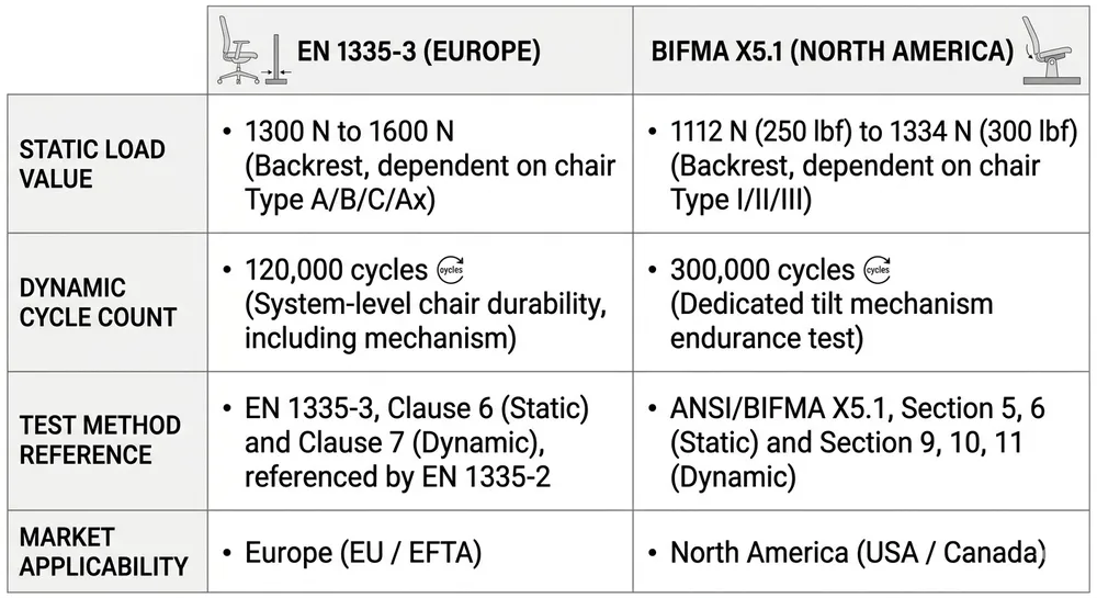
- EN 1335-3 (Europe): Defines static and dynamic load tests for office seating. Mechanisms sold into EU markets should be tested to this standard.
- BIFMA X5.1 (North America): The equivalent standard for the US and Canadian market. Static seat load test at 225 kg, dynamic durability at 100,000 cycles minimum.
- ANSI/BIFMA X5.1-2017: The current revision — confirm your supplier is referencing the right year.
A drawing that shows a load rating without referencing the test standard it was derived from is incomplete. "Rated to 150 kg" means nothing if you don't know whether that's a static proof load, a dynamic cycle test result, or a number someone wrote in because it sounded reasonable.
We run 100% functional testing on every mechanism before shipment, plus load-cycle verification on batch samples. The test parameters are documented against the drawing revision number, so if a drawing changes, the test record updates with it.
What to Request Before You Approve a Drawing
Most sourcing problems with chair mechanisms are visible in the drawing before production starts. The issue is that buyers don't know what to look for, and suppliers don't volunteer the gaps.
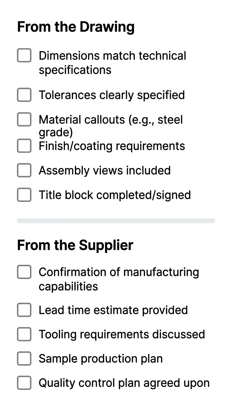
Before approving any chair mechanism drawing for production, request or confirm:
From the drawing itself:
- [ ] All critical dimensions have tolerances (not just nominal values)
- [ ] Material grades are specified by standard, not just by generic name
- [ ] Surface treatment includes thickness, pre-treatment, and salt spray rating
- [ ] Load rating references a named test standard and revision year
- [ ] Weld symbols are present on structural joints
- [ ] Hardware (bolts, springs, fasteners) is called out by grade or spec
From the supplier:
- [ ] Drawing revision number and date — confirm you have the current version
- [ ] Material test certificates (MTC) for steel components
- [ ] Surface treatment test report (salt spray, adhesion)
- [ ] Load test report referencing the applicable standard for your market
- [ ] RoHS declaration if selling into EU or regulated markets
If a supplier can't provide these documents, the drawing approval is premature. A complete drawing package with supporting test documentation is the minimum standard for a production order — not a premium service.
Common Drawing Gaps That Cause Production Problems
After 17 years of producing mechanisms for export markets, the gaps we see most often aren't random — they cluster around the same five areas.
1. Tolerance stacking on the tilt assembly Individual part tolerances look fine in isolation. But when you stack three or four components in the tilt path, the cumulative variation can exceed the functional range. A drawing review should check that the assembly tolerance chain closes correctly — meaning the worst-case combination of individual tolerances still produces a functional mechanism.
2. Spring spec without a load-deflection curve A spring callout that only states wire diameter and free length is incomplete. The spring rate (N/mm) determines the tilt resistance feel. Without a load-deflection curve or a stated spring rate, two batches from different spring suppliers can feel completely different to the end user.
3. Surface treatment on internal surfaces Drawings often specify coating on visible external surfaces but leave internal cavities and contact surfaces unspecified. On mechanisms with steel-on-steel sliding contact, uncoated internal surfaces corrode and cause binding within 12–18 months in humid environments. The drawing should specify treatment for all surfaces, not just the ones a customer can see.
4. Weld inspection class not stated Structural welds on mechanism housings should reference an inspection class (visual, dimensional, or NDT). A drawing that shows weld symbols without an inspection requirement leaves the quality standard undefined — which means it defaults to whatever the welder considers acceptable that day.
5. Hardware grade not called out Pivot bolts and adjustment screws on chair mechanisms carry real structural loads. A drawing that calls out "M8 bolt" without specifying grade (8.8, 10.9) is leaving a structural decision unspecified. Grade 8.8 and grade 10.9 bolts have meaningfully different yield strengths — the difference matters on a mechanism that cycles 100,000 times.
Reading a Drawing Revision History
Every production drawing should carry a revision block — a table in the title block that logs every change made to the drawing, with a date and a description of what changed.
This matters for sourcing because:
- If you approved Rev B and the supplier is producing from Rev C, you may have unknowingly accepted a specification change
- Revision history tells you whether a drawing has been through real engineering review or was created once and never updated
- When a quality issue occurs, the revision history is the first place to look for whether a known problem was already identified and corrected
Ask your supplier: "What revision is the current production drawing, and can you send me the revision history?" A supplier who can answer that question quickly has a controlled drawing system. A supplier who has to search for the answer probably doesn't.
We maintain ISO 9001:2015-compliant document control on all production drawings. Every revision is logged, every change is traceable, and buyers receive the current revision number with their order confirmation.
FAQ
What's the difference between a 2D drawing and a 3D model for chair mechanism sourcing?
For production approval, the 2D drawing is the controlling document. The 3D model (STEP or IGES file) is useful for fit-checking in your own CAD environment, but it doesn't carry tolerances, surface treatment specs, or material callouts in a legally binding way. Always approve the 2D drawing — not just the 3D model.
Can I use a competitor's mechanism drawing as a reference for a custom order?
Yes, with caveats. A reference drawing tells us the geometry you want. We'll redraw it to our own standards, add our material and treatment specs, and send you a new drawing for approval. We don't produce from third-party drawings directly — too many gaps, and the liability for specification errors becomes unclear.
How do I know if a mechanism drawing meets EN 1335 or BIFMA requirements?
The drawing itself won't tell you — the test report will. A drawing can reference a standard, but compliance is only confirmed by a test report from an accredited lab. If a supplier says their mechanism "meets BIFMA" but can't produce a test report, treat that as unverified.
What MOQ applies to custom mechanism drawings?
For standard mechanisms with minor modifications (mounting hole pattern, travel angle adjustment), MOQ is 500 units. For full custom tooling with new die-casting or progressive die work, we discuss tooling investment separately — typically amortized over the first production run. Request a quote with your drawing or reference spec and we'll give you a straight answer.
How long does drawing approval typically take?
We send a first drawing within 5–7 working days of receiving your requirements. Review cycles depend on how many revision rounds are needed — straightforward modifications usually close in one or two rounds. Complex custom mechanisms with new tooling take longer because we prototype before finalizing the drawing.